AutoCAD symbols are standardized graphic marks, text characters, and reusable drawing objects that communicate technical information without long written explanations. You may see them in architectural floor plans, mechanical drawings, electrical schematics, plumbing layouts, civil maps, welding details, and dimension notes.
A circle with a line may identify a light fixture, while Ø marks a diameter and ± indicates an allowable variation. Understanding these symbols helps designers create drawings that contractors, engineers, manufacturers, and inspectors can interpret correctly.
This guide explains what AutoCAD symbols mean, how they are created, where they come from, and how to choose the correct symbol for a professional drawing.
Quick Meaning:autocad symbols
AutoCAD symbols are graphic or text-based representations used to identify objects, measurements, materials, equipment, connections, and instructions in CAD drawings. They may appear as Unicode characters, dimension marks, line types, hatches, blocks, dynamic blocks, or intelligent symbols supplied by specialized AutoCAD toolsets.
AutoCAD Symbols Overview Table
| Field | Details |
| Symbol category | Technical drawing and CAD notation |
| Primary purpose | Communicate objects, dimensions, systems, and instructions |
| Common formats | Text characters, blocks, dynamic blocks, hatches, line types, tags, and annotations |
| Main industries | Architecture, engineering, construction, manufacturing, utilities, and product design |
| Software developer | Autodesk |
| Common file environment | DWG and DXF drawings |
| Basic text symbols | Degree °, plus-or-minus ±, diameter ∅, radius R, centerline ℄ |
| Common graphic symbols | Doors, windows, fixtures, outlets, valves, pumps, welds, and survey markers |
| Standardization | Often based on ISO, ANSI, ASME, IEC, IEEE, NFPA, or company standards |
| Unicode support | Available for many text and mathematical symbols |
| Emoji equivalent | None; technical symbols should not be replaced with emojis |
| Reusable AutoCAD format | Blocks, dynamic blocks, and tool-palette content |
| Main benefit | Faster drafting with consistent, readable technical information |
What Do AutoCAD Symbols Mean?
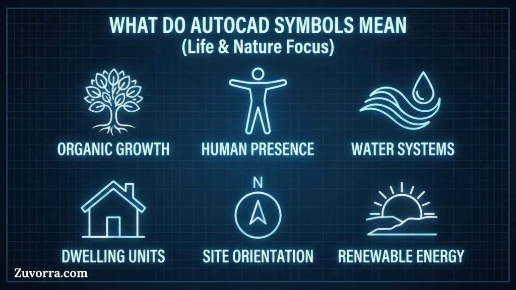
AutoCAD symbols represent real objects, design conditions, measurements, or technical instructions. Their exact meaning depends on the drawing discipline and the standard being followed.
For example:
- Ø placed before a number means diameter.
- R placed before a value means radius.
- ± defines a permitted positive or negative variation.
- A broken zigzag line may show that part of an object has been omitted.
- A triangle containing a number may point to a revision note.
- A circle with letters may identify a room, device, grid, or detail reference.
- A patterned area may represent concrete, earth, insulation, steel, or another material.
The term “AutoCAD symbol” does not describe one universal set of marks. AutoCAD provides the drawing environment, but industries and organizations determine what many symbols represent.
A symbol should therefore be read in context. The same circle, triangle, or line can carry different meanings in architectural, mechanical, electrical, and civil drawings.
Symbols, Blocks, and Icons Are Not the Same
These terms are often confused:
A symbol communicates technical meaning inside a drawing.
A block is a named collection of drawing objects that behaves as one reusable object. A block may contain a symbol, a title block, a piece of equipment, or an entire detail.
An interface icon appears in the AutoCAD ribbon, toolbar, status bar, or command area. It controls software functions and is not normally part of the final technical drawing.
Most complex drawing symbols are stored as blocks because blocks improve consistency and make repeated objects easier to insert and update.
History and Origin of AutoCAD Symbols
AutoCAD symbols developed from much older technical drawing practices. Builders, mapmakers, machinists, and engineers used graphic conventions long before computer-aided design existed.
Early Technical Drawing Conventions
Traditional drafting relied on ink, pencils, compasses, rulers, templates, lettering guides, and symbol stencils. A draftsman needed a consistent way to show hidden edges, centerlines, dimensions, materials, electrical devices, and mechanical components.
As engineering expanded across regions and industries, standardized drawing conventions became increasingly important. A manufacturer needed to interpret a drawing created by another office without guessing what every line meant.
International and national standards organizations developed rules for line types, projection methods, dimensioning, surface texture, geometric tolerancing, welding, electrical components, and other technical information.
ISO 128, for example, establishes general principles for technical product documentation and includes conventions for lines, views, and drawing presentation. Its purpose is to promote uniform graphic communication and facilitate the exchange of technical information.
From Paper Templates to CAD Libraries
When CAD systems became common, traditional symbols were recreated as digital geometry. Instead of tracing a stencil repeatedly, a drafter could insert a stored symbol and place it at the correct scale and orientation.
AutoCAD strengthened this approach through blocks. A group of lines, arcs, text, attributes, and other objects could be saved under a name and reused throughout a drawing.
Modern block libraries, tool palettes, and DesignCenter collections allow organizations to arrange approved symbols by discipline, project, or standard. Autodesk documentation describes block libraries as collections of block definitions and explains that tool palettes can organize blocks, hatches, and custom tools.
The Rise of Intelligent Symbols
Basic symbols are static geometry. Intelligent symbols can hold data and respond to drawing changes.
A dynamic door block might offer several widths and opening directions. An electrical component may contain a manufacturer code, terminal information, catalog number, and device tag. A room tag may display an area value drawn from the model or object data.
This development changed symbols from simple pictures into structured design information.
Symbolism and Interpretation in Technical Drawings
AutoCAD symbols do not usually carry mystical or emotional symbolism. Their meaning is functional: they compress detailed technical instructions into recognized visual forms.
Conventional Meaning
A conventional symbol has a meaning established by accepted professional practice. Examples include:
- A long-short-long line for a centerline
- A hidden line for an edge that cannot be seen in the current view
- A section arrow showing viewing direction
- A hatch pattern identifying a cut material
- An outlet symbol identifying an electrical receptacle
- A valve symbol describing a component in a piping system
The symbol works only when the reader understands the convention.
Project-Specific Meaning
Some symbols are defined for one project or organization. A company may design its own equipment tags, room codes, revision markers, safety indicators, or asset symbols.
Project-specific marks should appear in a legend, abbreviation sheet, or symbol schedule. Without a legend, unfamiliar symbols may cause costly misunderstandings.
Positive Function
Used correctly, symbols provide several benefits:
- They reduce repeated text.
- They save drawing space.
- They make plans easier to scan.
- They support consistent documentation.
- They improve coordination between disciplines.
- They reduce ambiguity during construction or manufacturing.
Negative Consequences of Poor Symbol Use
Symbols create risk when they are unclear, outdated, duplicated, or incorrectly scaled. Common problems include:
- Two symbols representing the same item
- One symbol carrying two meanings
- Symbols copied from an unknown source
- Missing legends
- Broken fonts or unsupported characters
- Excessive detail at a small plotting scale
- Blocks drawn in the wrong units
- symbols that do not match the governing standard
The practical lesson is simple: a symbol is useful only when its meaning is controlled and shared.
Psychological Interpretation
Technical symbols support visual recognition. A reader can often identify a familiar shape faster than they can read a sentence.
Shape and placement also create expectations. Arrows suggest direction, broken lines imply hidden or interrupted information, and enclosed tags usually point to referenced data. However, these visual clues do not replace a formal legend or drawing standard.
Cultural and Regional Significance
AutoCAD is used globally, but technical symbols are not always universal. Regional codes, industry standards, language conventions, and construction practices influence how drawings appear.
United States
US drawings frequently follow standards and practices associated with organizations such as ANSI, ASME, IEEE, NFPA, and the National CAD Standard. Architectural drawings often use feet and inches, while engineering projects may use decimal feet or metric units.
International and European Practice
Projects outside the United States commonly rely on ISO and IEC standards. Metric dimensions are widely used, and electrical or mechanical symbols may differ from those found in North American documentation.
AutoCAD Electrical supports multiple regional symbol libraries, including IEC, JIS, GB, and other standards, depending on installation and available content. Autodesk explains that additional regional and manufacturer libraries can be installed for the Electrical toolset.
Why Regional Differences Matter
A symbol that seems familiar may represent a different device under another standard. Electrical switches, contacts, circuit breakers, earth connections, and motors are common areas of variation.
For international work:
- Identify the governing code or standard.
- Use one approved symbol library.
- State the standard on the drawing set.
- Include a legend for project-specific marks.
- Avoid mixing conventions unless the difference is clearly documented.
Scientific and Technical Meanings of Common AutoCAD Symbols
Technical symbols are among the most important forms of notation used in AutoCAD.
Dimension and Measurement Symbols
| Symbol | Meaning | Example |
| ° | Degrees or angular measurement | 45° |
| ± | Plus-or-minus tolerance | 25 ± 0.2 mm |
| ∅ or Ø | Diameter | ∅20 mm |
| R | Radius | R10 |
| SR | Spherical radius | SR25 |
| S∅ | Spherical diameter | S∅50 |
| ℄ | Centerline | ℄ of shaft |
| ′ | Feet or minutes | 8′ |
| ″ | Inches or seconds | 6″ |
| % | Percentage or slope, depending on context | 2% slope |
| : | Ratio or scale | 1:50 |
AutoCAD supports Unicode strings and legacy control codes for several common text symbols. Autodesk lists %%d for degrees, %%p for plus-or-minus, and %%c for the diameter symbol. Their Unicode values include U+00B0, U+00B1, and U+2205.
Common AutoCAD Symbol Codes
| Desired symbol | Control code | Unicode entry |
| Degree ° | %%d | \U+00B0 |
| Plus-or-minus ± | %%p | \U+00B1 |
| Diameter ∅ | %%c | \U+2205 |
These codes are normally entered while creating or editing compatible text. Unicode is often more portable, but the selected font must contain the required character.
Architectural Symbols
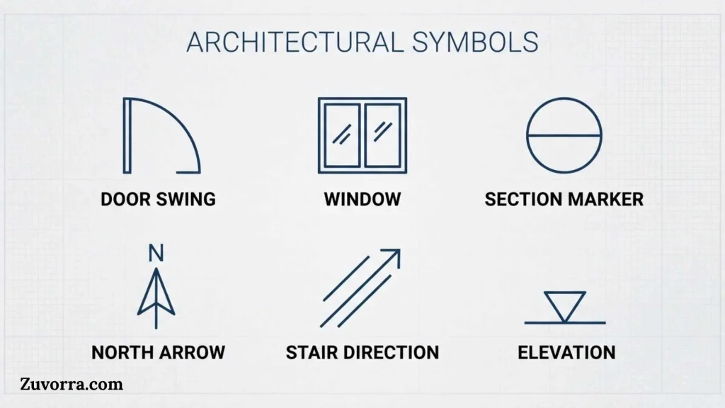
Architectural symbols represent building elements and spatial information. Common examples include:
- Door swings
- Windows
- Stairs and direction arrows
- Plumbing fixtures
- Elevation markers
- Section markers
- Detail callouts
- Room tags
- Grid bubbles
- North arrows
- Level markers
- Furniture and equipment
A door symbol does more than show a rectangle. Its arc indicates the direction in which the door opens. A section marker identifies where an imaginary cut passes through the building and directs the reader to another view.
Electrical Symbols
Electrical drawings use symbols for:
- Switches
- Receptacles
- Lights
- Motors
- Transformers
- Relays
- Contacts
- Circuit breakers
- Ground or earth connections
- Terminals
- Junction boxes
- Control devices
Standard AutoCAD and AutoCAD LT do not include every specialized industry library. Autodesk states that these products do not ship with extensive symbol libraries, although users can create libraries or obtain manufacturer-supplied blocks.
The AutoCAD Electrical toolset provides a much larger collection of intelligent electrical symbols. Autodesk currently describes the toolset as containing more than 65,000 electrical symbols, along with functions for wire numbering, component tagging, and reporting.
Mechanical and Manufacturing Symbols
Mechanical drawings use notation for:
- Diameter and radius
- Surface finish
- Welding
- Threads
- Countersinks
- Counterbores
- Depth
- Geometric dimensioning and tolerancing
- Datum references
- Fits and tolerances
- Sectioned materials
- Center marks
These marks must follow the selected drafting and manufacturing standard. A small change in a geometric tolerance frame can alter how a part is inspected or manufactured.
Plumbing and Piping Symbols
Plumbing, process, and piping drawings commonly include:
- Valves
- Pumps
- Tanks
- Strainers
- Drains
- Traps
- Pipe reducers
- Flow arrows
- Instrument bubbles
- Pipe connection types
- Hot, cold, waste, and vent lines
On a process and instrumentation diagram, a valve symbol may also show its actuation method, normal position, and control relationship.
Civil and Survey Symbols
Civil drawings may contain:
- Survey monuments
- Property corners
- Spot elevations
- Benchmarks
- Contours
- Utility lines
- Manholes
- Catch basins
- Trees
- Fire hydrants
- Road signs
- North arrows
- Slope indicators
Line types are especially important in civil work. Different patterns may distinguish water, gas, sewer, telecommunications, property boundaries, and existing or proposed features.
Where AutoCAD Symbols Are Used
AutoCAD symbols appear anywhere technical information must be communicated precisely.
Floor Plans
Floor plans use symbols for walls, openings, fixtures, appliances, furniture, alarms, outlets, and circulation. A symbol schedule often explains special devices or equipment.
Elevations and Sections
Elevation symbols identify heights, materials, finishes, and view references. Section drawings use cut lines, hatch patterns, and detail callouts to explain hidden construction.
Mechanical Parts
Manufacturing drawings use dimensions, tolerances, datum indicators, surface requirements, and feature-control frames to define how a part should be made and inspected.
Electrical Schematics
Schematic symbols show functional relationships rather than the physical appearance of equipment. Wires, contacts, relays, and devices are arranged to explain how a circuit operates.
Maps and Site Plans
Maps use north arrows, scale bars, property markers, contour labels, vegetation symbols, and utility indicators. The legend links each graphic mark to its meaning.
Construction Details
Detail symbols connect a location on a general drawing to an enlarged view. This prevents the main plan from becoming overloaded with small information.
Digital Asset Management
Organizations store approved symbols in block libraries, shared drawings, cloud libraries, DesignCenter folders, and tool palettes. AutoCAD allows blocks to be inserted through the Blocks palette, Tool Palettes, or DesignCenter.
Common Variations of AutoCAD Symbols
Static Blocks
A static block keeps the same geometry every time it is inserted. Users may rotate or scale it, but its internal form remains unchanged unless the block definition is edited.
Static blocks work well for simple symbols such as north arrows, section tags, and basic fixtures.
Dynamic Blocks
Dynamic blocks contain parameters, actions, or visibility states. One block may represent several sizes, orientations, or configurations.
For example, a dynamic window block may allow users to change its width, flip its direction, or choose between window types without loading several separate blocks.
Attributed Blocks
Attributed blocks store editable text data. A symbol might contain attributes for:
- Identification number
- Manufacturer
- Model
- Voltage
- Room name
- Equipment capacity
- Revision status
- Asset code
Attributes make schedules and data extraction more efficient.
Annotative Symbols
Annotative objects can display at controlled paper sizes across different viewport scales. This is useful for tags, callouts, and notes that must remain readable whether a view is plotted at 1:20, 1:50, or another scale.
Line-Type Symbols
Some symbols repeat as part of a line type. Examples include fence marks, utility letters, railroad patterns, gas lines, insulation, and property boundaries.
Hatch Symbols
Hatches use repeated patterns to show materials or zones. Common patterns represent earth, concrete, steel, wood, insulation, masonry, sand, and gravel.
A hatch pattern is not always a literal picture of the material. It is a graphic convention that should match the project standard.
User-Defined Symbols
Users can create custom symbols as blocks or custom arrowheads. AutoCAD’s Dimension Style Manager permits user-defined arrowhead blocks, provided the selected block exists in the drawing.
How to Choose the Correct Symbol

Use this decision guide before inserting a symbol:
Is the drawing governed by a published standard?
↓
Yes: Use the symbol required by that standard.
No: Continue to the next question.
Does your client or organization have a CAD manual?
↓
Yes: Use the approved library and layer settings.
No: Continue.
Is the symbol industry-specific?
↓
Yes: Check a recognized architectural, electrical, mechanical, civil, or piping reference.
No: Use a clear conventional symbol and define it in the legend.
Before finalizing the drawing, verify the symbol’s scale, units, layer, line weight, orientation, attribute values, and plotted appearance.
Common Misconceptions About AutoCAD Symbols
“AutoCAD Has Every Symbol Built In”
Standard AutoCAD includes drawing tools and some reusable content, but it does not provide a complete library for every profession. Specialized symbols may come from included toolsets, manufacturers, standards-based libraries, company templates, or custom blocks.
“Every AutoCAD Symbol Is Universal”
Many symbols vary by country, discipline, and standard. Never assume that a familiar electrical or plumbing mark has the same meaning on every project.
“A Block Is Always a Symbol”
A block can be a symbol, but it can also contain a title block, border, room layout, machine assembly, or detailed drawing. “Block” describes how the objects are stored, not what they mean.
“The Diameter Symbol and the Letter O Are Interchangeable”
They are not. The diameter symbol communicates a specific dimensional meaning. Replacing it with the letter O or a zero can create ambiguity.
“Scaling a Symbol Never Causes Problems”
Scaling may alter line weights, text size, hatch density, or annotation readability. Blocks created in different units can also enter a drawing at an unexpected size.
“Symbols Explain Themselves”
Even common marks may require a legend. Project-specific symbols should always be defined, especially when drawings will be reviewed by multiple disciplines or international teams.
“Any Downloaded Block Is Safe to Use”
Unverified blocks may contain incorrect units, unwanted layers, proxy objects, hidden geometry, excessive detail, or inaccurate technical information. Inspect outside content before adding it to an official library.
Interesting Facts About AutoCAD Symbols
- A symbol can be both graphic and data-rich.
An attributed or intelligent block may look simple while storing model numbers, descriptions, ratings, and identification tags. - Unicode improves text-symbol portability.
Unicode assigns standardized code points to characters such as degrees and plus-or-minus, although display still depends on font support. - The same geometry can carry several meanings.
A circle might represent a light, valve, instrument, connection point, detail reference, or survey marker. Context gives it meaning. - Symbols reduce language dependence.
Standard technical marks allow teams speaking different languages to interpret many parts of the same drawing. - A legend is part of the communication system.
It is not merely decorative. It connects project-specific graphics with precise definitions. - Dynamic blocks can replace many static symbols.
Visibility states and parameters allow one block to represent multiple configurations while keeping a library manageable. - Symbols can control schedules and reports.
When blocks include consistent attributes, their data can be extracted into equipment lists, door schedules, or component reports. - Line types can function as repeating symbols.
A utility line may combine dashes, gaps, letters, or shapes to communicate both location and service type. - Plot scale affects symbol design.
A symbol that looks clear in model space may become unreadable on paper. Good symbols are tested at their intended output size. - Electrical symbols may be schematic rather than physical.
Their purpose is to show circuit logic and connections, not necessarily the device’s real shape or installation position. - Approved libraries support quality control.
Shared blocks reduce the chance that different team members will invent inconsistent versions of the same symbol. - The simplest symbol is often the most effective.
Extra detail can make a plan harder to read and increase file size without adding useful information.
Related Symbols and Drawing Elements
Dimension Symbols
These include diameter, radius, angle, depth, tolerance, and centerline marks. They define measurable design requirements rather than physical objects.
Geometric Tolerance Symbols
These control form, orientation, location, and runout in manufacturing drawings. They belong to structured geometric dimensioning and tolerancing systems.
Welding Symbols
Welding symbols specify weld type, size, length, location, contour, and finishing requirements. Their placement along a reference line carries technical meaning.
Electrical Schematic Symbols
These identify circuit components and functional connections. They differ from panel footprints, which show physical equipment arrangements.
Architectural Callout Symbols
Section, elevation, and detail markers direct readers to related views elsewhere in a drawing set.
Map Symbols
North arrows, contour lines, utility markers, and boundary patterns communicate geographic orientation and site conditions.
Hatches
Hatches represent materials, surfaces, zones, or cut areas. Unlike a single block symbol, a hatch fills a defined boundary.
Interface Icons
AutoCAD interface icons operate commands such as Line, Move, Trim, or Hatch. They should not be confused with symbols placed in the drawing itself.
Frequently Asked Questions
What are AutoCAD symbols?
AutoCAD symbols are graphic marks, text characters, blocks, line patterns, or annotations used to represent real objects and technical instructions. They may identify doors, electrical devices, valves, dimensions, materials, welds, equipment, or drawing references. Their meaning depends on the discipline and governing drafting standard.
Where can I find symbols in AutoCAD?
You can access reusable content through the Blocks palette, Tool Palettes, and DesignCenter. Entering TOOLPALETTES or pressing Ctrl+3 opens Tool Palettes in standard Windows installations. Available content varies by product, toolset, template, installation, and any custom libraries added by your organization.
How do I insert the diameter symbol in AutoCAD?
While editing supported text, enter %%c or use the Unicode string \U+2205. You can also insert it from the text editor’s Symbol menu. Check the displayed character because some fonts visually distinguish the diameter sign, empty-set symbol, and slashed letter O differently.
What is the AutoCAD code for the degree symbol?
The traditional AutoCAD control code is %%d. The corresponding Unicode entry is \U+00B0. Both methods produce the degree symbol in supported text environments. Use the symbol for angular dimensions, geographic coordinates, temperatures, or other values where degrees are the approved unit.
What is the code for plus-or-minus in AutoCAD?
Enter %%p to create the plus-or-minus symbol, or use the Unicode string \U+00B1. In technical drawings, ± usually introduces a bilateral tolerance, such as 20 ± 0.1 mm. The value permits the measured feature to vary equally above or below its nominal size.
Does AutoCAD include electrical symbols?
Standard AutoCAD does not contain every specialized electrical library. The AutoCAD Electrical toolset supplies extensive schematic and panel symbols plus intelligent functions for component tagging and wire data. AutoCAD LT users generally need custom blocks or a suitable third-party or manufacturer library for specialized electrical content.
How do I create my own AutoCAD symbol?
Draw the required geometry at the correct units, assign appropriate layers and properties, and use the BLOCK command to create a named block. Add attributes when the symbol needs editable data. Test insertion, rotation, scaling, plotting, and visibility before adding it to a shared library or tool palette.
What is the difference between a block and a dynamic block?
A standard block contains reusable geometry with a fixed internal form. A dynamic block includes parameters and actions that allow controlled changes, such as stretching, flipping, rotating, choosing a visibility state, or changing a component size. Dynamic blocks can reduce the number of separate files needed in a symbol library.
Why do AutoCAD symbols appear as boxes or question marks?
The selected text font may not support the required Unicode character, or the drawing may reference a missing font file. Try an appropriate Unicode-compatible font and confirm that all required fonts are installed. Avoid replacing technical symbols blindly, because a visually similar character may carry a different meaning.
How can I keep symbols consistent across a project?
Create a controlled block library, use approved templates, assign standard layers, define naming rules, and distribute the same tool palettes to all team members. Include a legend in the drawing set and review external blocks before use. A designated CAD manager should approve revisions to shared symbols.
Key Takeaways
- AutoCAD symbols communicate technical objects, measurements, systems, and instructions.
- Symbols may appear as text characters, blocks, dynamic blocks, hatches, line types, or intelligent components.
- Common text codes include %%d for degrees, %%p for plus-or-minus, and %%c for diameter.
- Symbol meanings vary across architecture, electrical design, mechanical engineering, civil work, and piping.
- International, national, client, and company standards determine which symbols should be used.
- Standard AutoCAD does not contain every specialized symbol library.
- Blocks make symbols reusable, while attributes and dynamic features add data and flexibility.
- Project-specific symbols should be defined in a legend.
- Every symbol should be checked for units, scale, layer, orientation, and plotted readability.
- Unverified downloaded blocks can introduce technical errors and drawing problems.
Conclusion
AutoCAD symbols form a compact visual language for technical design. They help professionals describe dimensions, materials, equipment, connections, locations, and construction instructions without filling drawings with repeated text.
Their value comes from consistency, not appearance alone. The correct mark must follow the project’s discipline, standard, scale, and documentation rules. A diameter sign, electrical component, door swing, valve, or section marker only works when everyone reading the drawing understands it in the same way.
By combining recognized conventions with controlled block libraries, clear legends, and careful quality checks, designers can use AutoCAD symbols to create drawings that are faster to produce, easier to read, and safer to build from.
References
- Autodesk, “Text Symbols and Special Characters Reference.” Lists AutoCAD control codes and Unicode values for degree, plus-or-minus, and diameter symbols.
- Autodesk, “About Organizing Blocks.” Explains block libraries and reusable block organization.
- Autodesk, “About Creating Tool Palettes.” Describes organizing blocks, hatches, and custom tools through palettes and DesignCenter.
- Autodesk Support, “Where to Find Symbol Libraries for AutoCAD Products?” Clarifies the availability of symbol libraries in AutoCAD and AutoCAD LT.
- Autodesk, “Electrical Toolset in Autodesk AutoCAD.” Describes the electrical symbol library and intelligent electrical-design features.
- International Organization for Standardization, ISO 128 series, “Technical Product Documentation.” Establishes general drawing presentation and line conventions.
- International Organization for Standardization, ISO 7083:2021, “Symbols Used in Technical Product Documentation.” Provides an index connecting technical drawing symbols with their governing standards.

I’m Rupert Ashbourne, a British author interested in how symbols have shaped human communication throughout history. I examine signs, emblems, markings, and visual representations, explaining their meanings and cultural significance. My aim is to make symbolism approachable while helping readers understand how simple shapes and images can carry surprisingly powerful messages.
Books:
- The Meaning of Symbols
- A History of Signs and Emblems