
HVAC electrical symbols are standardized marks used to represent motors, switches, relays, transformers, sensors, protective devices, and control components on wiring diagrams. They allow technicians, engineers, installers, and students to understand how heating, ventilation, air-conditioning, and refrigeration equipment operates without drawing every physical part.
You may encounter these symbols on furnace wiring diagrams, air-handler schematics, rooftop-unit plans, heat-pump service panels, control drawings, building automation diagrams, and equipment manuals. Learning how they connect is often more useful than memorizing each shape by itself because the diagram reveals how power, safety controls, and operating commands move through the system.
Quick Meaning
HVAC electrical symbols are graphical representations of electrical and control components used in heating, cooling, ventilation, and refrigeration systems. They identify devices such as compressors, fan motors, contactors, thermostats, capacitors, switches, fuses, sensors, and transformers while showing how those devices are electrically connected.
HVAC Electrical Symbols Overview Table
| Field | Details |
| Symbol group | HVAC electrical and control symbols |
| Primary meaning | Components and electrical relationships within HVAC equipment |
| Main categories | Power, control, protection, motors, switches, sensors, relays, and wiring |
| Common diagram types | Schematic, ladder, connection, single-line, block, and pictorial diagrams |
| Typical applications | Furnaces, heat pumps, air conditioners, chillers, boilers, rooftop units, and control panels |
| Common standards | IEC 60617, ANSI-related drawing practices, manufacturer conventions, and project legends |
| Main users | HVAC technicians, electricians, controls engineers, designers, inspectors, and students |
| Modern use | Printed schematics, CAD drawings, BIM models, digital service manuals, and building automation systems |
| Unicode equivalent | Usually not applicable; most are technical drawing symbols rather than text characters |
| Related symbol groups | Electrical schematic symbols, electronic symbols, piping symbols, and HVAC mechanical symbols |
The International Electrotechnical Commission maintains IEC 60617 as an international database of graphical symbols for electrotechnical diagrams. IEC describes these symbols as a standardized visual language for representing electrical functions and relationships.
What Do HVAC Electrical Symbols Mean?
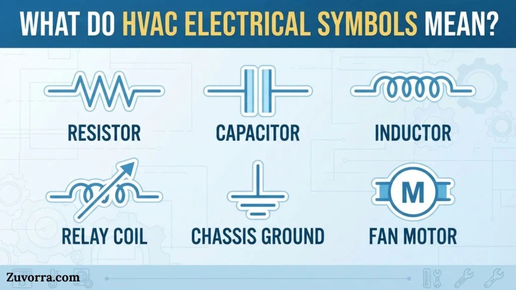
HVAC electrical symbols show what each component does and how electricity moves through a system. A symbol may represent a physical device, such as a compressor motor, or a control function, such as a temperature-activated switch.
The symbols do not always resemble the actual parts. A contactor may be a large device with wires and terminals, yet its diagram representation may consist of a coil and several separate contact symbols. The drawing emphasizes electrical behavior rather than physical appearance.
Most symbols fall into five functional groups:
- Power-source symbols identify incoming voltage, transformers, batteries, hot conductors, neutral conductors, and grounding points.
- Load symbols represent components that consume power, including motors, compressors, heaters, solenoids, and indicator lamps.
- Control symbols show thermostats, pressure switches, relays, contactors, timers, sensors, and control-board outputs.
- Protection symbols represent circuit breakers, fuses, overload protectors, disconnects, and safety switches.
- Connection symbols show wires, terminals, splices, plugs, junctions, and crossing conductors.
The real meaning of any symbol depends on its position, label, nearby contacts, and the diagram legend. For example, a simple circle may represent a motor, lamp, terminal, or another device depending on the letters and lines around it.
History and Origin of HVAC Electrical Symbols
HVAC electrical symbols developed from the broader language of electrical engineering drawings. As electrical systems became more complex during the late nineteenth and twentieth centuries, engineers needed a practical way to document circuits without drawing realistic pictures of every switch, motor, and wire.
Early equipment diagrams often used pictorial drawings. These images helped installers recognize components, but they became difficult to follow as systems gained more relays, safety controls, and automatic sequences.
Schematic symbols solved that problem. Instead of showing what a part looked like, the drawing showed what the part did. A switch appeared as opening or closing contacts. A transformer appeared as coupled windings. A motor became a labeled load symbol. This functional approach allowed technicians to trace circuits much faster.
Heating and refrigeration systems gradually adopted the same visual language. Basic furnaces needed only a few controls, but later equipment introduced:
- Automatic gas valves
- Blower relays
- High-limit switches
- Compressor contactors
- Defrost controls
- Pressure switches
- Electronic ignition modules
- Variable-speed drives
- Microprocessor control boards
- Building automation networks
International standardization eventually improved consistency across industries. IEC 60617 now covers graphical symbols for conductors, switching devices, passive components, machines, transformers, semiconductor devices, logic functions, and other electrotechnical elements. The IEC directs standards developers to use IEC 60617 symbols when preparing electrotechnical diagrams.
HVAC drawings also use industry-specific symbols and abbreviations. ASHRAE maintains terminology, nomenclature, units, abbreviations, and symbols for heating, ventilation, air-conditioning, water-heating, and refrigeration work.
How HVAC Electrical Symbols Are Interpreted
HVAC symbols are best understood as a visual operating language. Each shape provides one piece of information, while the circuit arrangement explains the complete sequence.
Power symbols
Power symbols identify the electrical source feeding the system.
Common markings include:
- L1 and L2: Line-voltage conductors
- L1, L2, and L3: Three-phase power conductors
- N: Neutral
- G or ground symbol: Equipment grounding connection
- R and C: Common low-voltage transformer terminals
- 24 VAC: Typical control-circuit voltage
- 120 V, 208 V, 230 V, 240 V, 277 V, or 460 V: Equipment power ratings
Voltage labels matter because one diagram may contain both high-voltage and low-voltage circuits. A rooftop unit, for example, may use 460-volt power for motors and 24-volt power for thermostats and relays.
Wire and connection symbols
A straight line usually represents a conductor. A solid dot where lines meet normally indicates an electrical junction.
Two lines crossing without a connection may be shown with:
- No junction dot
- A small bridge or arc
- A drawing convention explained in the legend
Never assume crossed lines are connected. Always inspect the junction markings and diagram key.
Switch symbols
Switches control whether current can pass through part of a circuit. HVAC systems use both manually operated and automatically operated switches.
Common types include:
- On-off switches
- Disconnect switches
- Door interlock switches
- Float switches
- Pressure switches
- Temperature switches
- Airflow switches
- Limit switches
The symbol normally shows contacts in their normal state, meaning the state that exists before the device is energized or acted upon by its operating condition.
Normally open contacts
A normally open contact does not conduct electricity in its normal position. It closes after the relay, contactor, pressure device, thermostat, or other mechanism operates.
Applications include:
- Calling a compressor
- Starting a fan
- Energizing a heating stage
- Activating a humidifier
- Completing a pump circuit
Normally closed contacts
A normally closed contact allows current to flow under normal conditions. It opens when the controlling device operates.
This arrangement often appears in safety circuits. Examples include:
- High-pressure cutout
- Low-pressure cutout
- Furnace high-limit switch
- Condensate overflow switch
- Motor overload contact
- Flame-rollout switch
A normally closed safety chain allows equipment to operate only while every required safety device remains in its safe position.
Common HVAC Electrical Symbols and Their Functions
Motor symbol
A motor is commonly represented by a circle containing the letter M or by a labeled circular symbol.
HVAC motors drive:
- Indoor blowers
- Outdoor condenser fans
- Pumps
- Compressors
- Exhaust fans
- Cooling-tower fans
- Dampers and valves
Letters may identify a specific function, such as BM for blower motor, CFM for condenser-fan motor, or IDM for induced-draft motor. Manufacturer abbreviations vary.
Compressor symbol
The compressor may appear as a motor symbol, a specialized compressor mark, or a labeled block. Labels such as COMP, CPR, or C may be used.
The compressor is the main electrical load in many cooling and heat-pump systems. Its circuit commonly includes:
- A contactor
- An overload protector
- A run capacitor
- A start capacitor or start relay
- Pressure switches
- A crankcase heater
- Control-board protection logic
Transformer symbol
A transformer is represented by two electrically separate windings placed close together. Core lines may appear between the windings.
In HVAC equipment, a control transformer commonly reduces line voltage to 24 VAC. The primary side receives equipment voltage, while the secondary side supplies thermostats, relays, contactors, gas valves, and control boards.
Relay coil
A relay coil may be shown as a circle, rectangle, or coil shape with identifying letters or numbers.
When voltage energizes the coil, its associated contacts change position. Those contacts may appear elsewhere on the diagram but share the same identifying label.
For example, energizing relay coil R1 may close an R1 normally open contact and open an R1 normally closed contact in another section.
Contactor
A contactor is an electrically operated switch designed to control a larger load. HVAC contactors commonly start compressors, condenser fans, heaters, and large motors.
Its diagram typically includes:
- A low-voltage or line-voltage coil
- One or more power contacts
- Optional auxiliary contacts
The power contacts may appear separately from the coil. Matching labels show that they belong to the same device.
Capacitor
A capacitor is commonly represented by two parallel plates. A polarized capacitor may have a curved plate or polarity marking.
HVAC systems may use:
- Run capacitors
- Start capacitors
- Dual-run capacitors
- Power-factor correction capacitors
A dual-run capacitor has three terminal groups, often marked C, FAN, and HERM. “HERM” refers to the hermetically sealed compressor.
Resistor
A resistor may appear as a zigzag line in many North American drawings or as a rectangle in IEC-style drawings.
Resistors limit current, divide voltage, create heat, or form part of sensing and timing circuits. Thermistors are temperature-sensitive resistors commonly used in modern HVAC control systems.
Fuse
A fuse is represented by a small rectangular or line-based symbol placed in series with a conductor. It opens the circuit when excessive current causes its internal element to melt.
Fuses protect transformers, control boards, motors, compressors, and branch circuits. Replacing a fuse with a higher rating can defeat the intended protection and create a serious hazard.
Circuit breaker
A circuit-breaker symbol resembles a switching device with protective operation. It may be labeled CB.
Circuit breakers protect conductors and equipment from overcurrent conditions. Unlike a fuse, a circuit breaker can usually be reset after the fault has been identified and corrected.
The National Electrical Code is a benchmark for safe electrical design and installation, but it is not a symbol dictionary. Diagram symbols and electrical installation rules serve related but different purposes.
Ground symbol
The protective-earth or grounding symbol identifies a connection intended to reduce shock and fault hazards. It is usually drawn as stacked horizontal lines that decrease in width.
A ground symbol should not automatically be treated as a current-carrying neutral. Equipment ground and neutral serve different functions even though they may be bonded at a designated point in the electrical system.
Thermostat symbol
A thermostat may appear as a temperature-operated switch, a rectangular controller, or a terminal block labeled with thermostat letters.
Common low-voltage terminal designations include:
| Terminal | Typical Function |
| R | 24-volt power from transformer |
| C | Common side of transformer |
| Y or Y1 | First-stage cooling or compressor |
| Y2 | Second-stage cooling |
| G | Indoor fan |
| W or W1 | First-stage heating |
| W2 | Second-stage heating |
| O | Reversing valve energized in cooling |
| B | Reversing valve or another manufacturer-defined function |
| AUX | Auxiliary heat |
| E | Emergency heat |
| L | System monitor or fault indicator |
Terminal letters are conventions, not universal guarantees. Equipment documentation must take priority, especially for heat pumps and communicating controls.
Pressure switch
A pressure switch changes contact state when pressure rises above or falls below a set value.
HVAC applications include:
- Furnace draft-proving switches
- Refrigerant high-pressure switches
- Refrigerant low-pressure switches
- Filter differential-pressure switches
- Water-pressure safeties
The diagram may show normally open or normally closed contacts along with an abbreviation such as HPS, LPS, or PS.
Limit switch
A limit switch opens or closes when a temperature or mechanical condition reaches a set point.
Furnaces commonly use high-limit switches to interrupt burner operation if the heat exchanger or supply-air region becomes too hot. Flame-rollout switches monitor abnormal flame or heat conditions near burner compartments.
Solenoid valve
A solenoid valve symbol combines a valve function with an electromagnetic actuator. In electrical diagrams, it may appear mainly as a coil labeled for the controlled valve.
Examples include:
- Gas valves
- Refrigerant solenoid valves
- Hot-water valves
- Steam valves
- Humidifier water valves
Heater element
An electric heating element is commonly shown as a zigzag, coil, or resistive load symbol.
Multiple elements may be staged through relays, contactors, sequencers, or solid-state controls to reduce sudden electrical demand.
Indicator lamp
A lamp is often drawn as a circle with an X or filament-like mark inside. It may indicate:
- Power available
- Heating active
- Cooling active
- Alarm present
- Filter service required
- Safety circuit open
Terminal and connector
A terminal may appear as a circle, numbered connection point, or labeled block. Plugs and sockets may use matching letters or numbers.
Terminal markings help technicians determine where field wiring ends and factory wiring begins.
Scientific and Technical Meaning
HVAC electrical symbols describe three technical ideas at the same time: component identity, circuit state, and functional relationship.
Component identity
The shape and label identify the device. A motor symbol represents an electrical machine. A fuse symbol represents an overcurrent-protection device. A pressure-switch symbol represents a switch operated by pressure.
Circuit state
Contact symbols show whether the current path is open or closed in the device’s normal condition. This information allows a technician to predict voltage at different points before and after the system receives a call.
Functional relationship
Matching labels connect coils with their contacts, sensors with controllers, and outputs with loads. The components may not appear next to one another because schematics organize circuits by function rather than by physical location.
This is why a schematic should not be read as a map of the cabinet. A component shown near another symbol on paper may be located several feet away in the actual unit.
Major Types of HVAC Electrical Diagrams
Schematic diagram
A schematic shows electrical operation. It is the best drawing for tracing current and understanding sequence.
Use it to answer questions such as:
- What must close before the compressor starts?
- Which safety switch interrupts the gas valve?
- What relay energizes the blower?
- Why does a contactor fail to receive control voltage?
Ladder diagram
A ladder diagram places supply rails on opposite sides with control circuits arranged as horizontal rungs.
The reader typically follows each rung from the energized side toward the return side. Ladder diagrams are common in commercial equipment, industrial controls, motor circuits, boilers, and air-handling systems.
Wiring or connection diagram
A wiring diagram shows terminals, wire colors, connector numbers, and physical connections. It is especially useful when replacing a component or reconnecting field wiring.
Pictorial diagram
A pictorial diagram uses realistic images or simplified drawings of components. It helps beginners locate parts but usually provides less detail about circuit logic.
Single-line diagram
A single-line diagram simplifies a multi-conductor power system into one representative line. It is common in building power distribution, switchgear, motor-control centers, and large mechanical plants.
Block diagram
A block diagram shows broad relationships between controllers, sensors, networks, and equipment without displaying every conductor.
It is often used for building automation systems and direct digital control architecture.
Where HVAC Electrical Symbols Are Used
HVAC electrical symbols appear anywhere professionals need to design, install, operate, or troubleshoot equipment.
Common locations include:
- Equipment access-panel diagrams
- Installation manuals
- Service manuals
- Construction drawings
- Electrical plans
- Mechanical plans
- Building automation drawings
- Control-panel documentation
- Shop drawings
- BIM models
- Commissioning reports
- Training textbooks
- Refrigeration-system schematics
- Boiler-control drawings
- Chiller-control diagrams
- Motor-control-center plans
ASHRAE training materials treat electricity, sensors, valves, dampers, electric controls, control diagrams, sequences, and direct digital control as connected parts of HVAC system design and operation.
How to Read an HVAC Electrical Diagram Step by Step
1. Read the title block and legend
Identify the equipment model, drawing revision, voltage, symbol definitions, and abbreviations.
Never rely only on a generic symbol chart when the manufacturer supplies a project-specific legend.
2. Find the power source
Locate L1, L2, L3, neutral, transformer secondary, or another power designation.
Determine whether the circuit is line voltage, low voltage, direct current, or a communication circuit.
3. Identify the major loads
Find the compressor, blower motor, condenser-fan motor, pumps, electric heaters, gas valve, and other energy-consuming components.
4. Locate the controlling devices
Trace backward from each load to its contactor, relay, transistor output, switch, or controller.
5. Follow the safety chain
Look for overloads, pressure switches, limit switches, float switches, airflow switches, and interlocks.
A load cannot operate when a required series safety contact remains open.
6. Check the normal position of contacts
Determine which contacts are normally open and which are normally closed.
Remember that “normal” usually means the coil is de-energized and the operating condition has not activated the switch.
7. Match labels across the drawing
A coil marked K1 may control contacts labeled K1 in several locations. A sensor marked TS1 may connect to a controller input elsewhere.
8. Compare the diagram with the actual unit
Confirm terminal numbers, wire labels, connector locations, and component markings before testing.
Quick Decision Guide for Identifying an Unknown Symbol
Does the symbol interrupt a conductor?
↓
It is likely a switch, contact, fuse, breaker, or protective device.
Does it contain a coil, circle, or actuator label?
↓
It may be a relay, contactor, solenoid, or motor.
Does it show two nearby windings?
↓
It is probably a transformer.
Does it show two parallel plates?
↓
It is likely a capacitor.
Does it respond to temperature, pressure, level, or airflow?
↓
Look for a sensor or condition-operated switch label.
Is the shape unclear?
↓
Check the legend, abbreviation list, terminal schedule, and manufacturer manual before drawing a conclusion.
Common Variations in HVAC Symbols
HVAC symbols are not completely identical across all countries, manufacturers, and drawing systems.
ANSI-style and IEC-style variations
North American drawings often use zigzag resistor symbols, while IEC-style diagrams commonly use rectangular resistor symbols. Switches, motors, and control devices may also be drawn differently.
Manufacturer-specific abbreviations
One manufacturer may label a condenser-fan motor CFM, while another uses OFM for outdoor-fan motor. A compressor contactor may appear as CC, C, M1, or K1.
Simplified control-board symbols
Modern equipment may represent an entire electronic control board as a rectangle with labeled inputs and outputs. Internal relays, processors, and logic functions may not be shown.
Dual-purpose symbols
A circle alone does not have one fixed meaning. Letters, terminal numbers, and surrounding conductors complete the interpretation.
Regional wire-color differences
Wire colors may follow manufacturer practices, local conventions, or national requirements. Color supports identification but should never replace voltage testing and diagram verification.
Similar Symbols That Are Easy to Confuse
| Symbol or Device | Common Confusion | Key Difference |
| Relay | Contactor | A contactor typically switches larger loads |
| Fuse | Circuit breaker | A fuse must be replaced; a breaker is usually resettable |
| Neutral | Equipment ground | Neutral normally carries return current; ground is primarily protective |
| Normally open contact | Open safety device | “Normally open” describes design state, not necessarily a fault |
| Transformer | Two separate coils | A transformer symbol shows magnetic coupling |
| Capacitor | Battery | Capacitor plates are similar, but battery cells use unequal line lengths |
| Thermistor | Standard resistor | A thermistor changes resistance with temperature |
| Pressure switch | Thermostat contact | The operating condition differs even if contact shapes look similar |
| Wire crossing | Electrical junction | A junction normally has a dot or another stated connection mark |
Common Misconceptions
Every drawing uses identical symbols
It does not. Standards improve consistency, but manufacturers and engineering firms may use their own approved legends and abbreviations.
Symbols show physical component locations
Schematics show electrical relationships. Wiring and pictorial diagrams are better for locating components.
An open contact always indicates failure
An open contact may be operating exactly as designed. A normally open thermostat contact, for example, remains open until there is a demand.
All HVAC control circuits use 24 volts
Many residential systems use 24 VAC controls, but commercial and industrial systems may use other AC voltages, DC circuits, network signals, pneumatic controls, or manufacturer-specific communication buses.
Wire color proves electrical function
Colors can help, but wires may be replaced, faded, spliced, or used differently. Confirm function with the diagram, terminal labels, and appropriate testing.
A schematic authorizes electrical work
A diagram explains a circuit, but it does not replace training, safe work procedures, equipment instructions, or applicable codes. NFPA describes the NEC as a benchmark for safe electrical design, installation, and inspection.
Interesting Facts About HVAC Electrical Symbols
- One relay may appear several times on the same drawing.
The coil can appear on one rung while its contacts appear on other rungs. Matching labels reveal that they belong to one device. - Symbols describe function more than appearance.
A small contact symbol may represent part of a contactor large enough to switch a compressor motor. - The normal state is not always the operating state.
Contacts are generally drawn before the coil is energized or the sensing condition acts on the device. - Safety controls often appear in series.
This arrangement means every required switch must be closed before the controlled load can operate. - A dot can change the meaning of an entire circuit.
At crossing conductors, a junction dot may determine whether two circuits connect or remain electrically separate. - Low-voltage and high-voltage circuits may share one sheet.
Transformers divide the two sections, so voltage labels are essential. - Modern digital systems still depend on symbols.
Even when software controls the equipment, drawings still use symbols for sensors, outputs, power supplies, communication links, and field devices. - IEC 60617 functions as a symbol database rather than one small chart.
The current IEC database contains more than 1,500 graphical symbols organized by shape and function. - Equipment legends outrank memory.
A familiar-looking symbol may have a special meaning on a particular drawing, so the project legend remains the first authority. - A wiring diagram and a schematic can describe the same unit differently.
The wiring diagram emphasizes terminals and conductors, while the schematic emphasizes operating logic. - Contact labels make complex diagrams readable.
A technician can connect separated relay contacts to their controlling coil without tracing a physical mechanical linkage. - HVAC symbols overlap several technical fields.
A single drawing may combine electrical, refrigeration, airflow, plumbing, instrumentation, and digital-control notation.
Related HVAC and Electrical Symbols
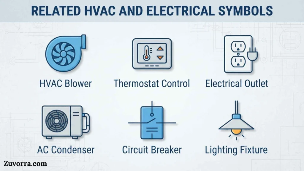
Mechanical HVAC symbols
These represent ducts, fans, filters, dampers, coils, diffusers, grilles, pumps, valves, and equipment on floor plans and system drawings.
Refrigeration symbols
Refrigeration diagrams use symbols for compressors, condensers, evaporators, expansion devices, receivers, accumulators, check valves, and service ports.
Piping and instrumentation symbols
Piping and instrumentation diagrams show process piping, valves, instruments, sensors, control loops, and flow relationships.
Electronic symbols
Electronic schematics include diodes, transistors, integrated circuits, logic gates, rectifiers, and circuit-board components.
Building automation symbols
These represent controllers, network trunks, input-output points, temperature sensors, pressure sensors, actuators, gateways, and supervisory systems.
Electrical plan symbols
Building plans show outlets, panels, disconnects, lighting, switches, junction boxes, feeders, and equipment connections.
Frequently Asked Questions
What are the most important HVAC electrical symbols to learn first?
Start with wires, junctions, grounds, transformers, motors, capacitors, relay coils, contactor contacts, fuses, breakers, thermostats, and normally open and normally closed switches. These components appear in many residential and commercial diagrams and provide the foundation for tracing more advanced control sequences.
How can I tell whether a switch is normally open or normally closed?
Look at the contact symbol in its unoperated state. A visible gap usually indicates a normally open contact, while touching contact elements indicate a normally closed contact. Always check the legend because drawing styles vary, and remember that “normal” refers to the device before activation.
What does a circle with the letter M mean?
A circle containing M usually represents an electric motor. Nearby labels may identify the motor’s purpose, such as blower, pump, compressor, or condenser fan. Confirm the meaning through the legend because circles may represent other components when they contain different letters or markings.
What does a dot on an HVAC wiring diagram mean?
A solid dot where conductors meet normally indicates an electrical connection or splice. Crossing lines without a dot are often not connected, although drawing conventions differ. Check the diagram legend, especially on older or crowded schematics where bridges, arcs, or special crossing marks may be used.
What do R, C, Y, G, and W mean on a thermostat diagram?
R usually supplies 24-volt control power, and C is the common side of the transformer. Y commonly calls for cooling, G starts the indoor fan, and W calls for heating. Heat pumps and communicating systems may assign additional or manufacturer-specific functions.
Why are relay contacts drawn separately from the relay coil?
Separating the contacts allows the schematic to place each contact where it operates electrically. The coil and contacts remain linked by matching identifiers, such as R1 or K1. This makes complex circuits easier to read than drawing long mechanical lines between every connected part.
Are HVAC symbols the same as standard electrical symbols?
Many are standard electrical symbols because HVAC equipment uses motors, transformers, relays, switches, fuses, capacitors, and other common devices. HVAC diagrams also include specialized controls, equipment abbreviations, thermostat terminals, pressure safeties, and building automation points that may not appear on basic electrical charts.
What is the difference between a schematic and a wiring diagram?
A schematic explains how the electrical circuit functions, while a wiring diagram shows how wires connect to actual terminals and components. Use a schematic for sequence troubleshooting and a wiring diagram for installation, replacement, connector identification, and physical reconnection.
Can I troubleshoot HVAC equipment using only a symbol chart?
A chart can help identify components, but safe troubleshooting also requires the correct equipment diagram, manufacturer instructions, voltage information, testing procedures, and technical knowledge. Generic symbols cannot reveal every terminal assignment, software condition, safety requirement, or manufacturer-specific control sequence.
Which standard covers electrical diagram symbols?
IEC 60617 is a major international source for graphical symbols used in electrotechnical diagrams. North American drawings may also follow ANSI-related practices, engineering-office standards, and manufacturer conventions. The correct project legend should always be used alongside any general standard.
Key Takeaways
- HVAC electrical symbols represent components, connections, operating states, and control relationships.
- Major symbol groups include power sources, loads, switches, controls, protective devices, and conductors.
- A symbol’s label and circuit position are often as important as its shape.
- Normally open and normally closed contacts are drawn in their unoperated state.
- Schematics explain operation, while wiring diagrams emphasize physical connections and terminals.
- Relay coils and their contacts may appear in different locations but share matching labels.
- Manufacturer legends should take priority over generic symbol charts.
- IEC 60617 provides an international system of graphical symbols for electrotechnical diagrams.
- Electrical codes address safe design and installation but do not replace equipment-specific schematics.
- Accurate diagram reading requires tracing power, loads, controls, safeties, and return paths in sequence.
Conclusion
HVAC electrical symbols turn complex circuits into a readable visual language. Once you recognize the basic marks for motors, transformers, switches, relays, capacitors, protective devices, sensors, and wiring connections, you can begin tracing how an HVAC system receives power, responds to a thermostat, proves safe operating conditions, and energizes each load.
The most reliable approach is not to memorize isolated shapes. Read the legend, identify the voltage source, follow the circuit in order, match device labels, and compare the drawing with the actual equipment. Used this way, HVAC electrical symbols become practical tools for understanding installation, control, maintenance, and troubleshooting.
References
- International Electrotechnical Commission. IEC 60617: Graphical Symbols for Diagrams.
- International Electrotechnical Commission. Graphics and Figures Guidance.
- International Electrotechnical Commission Technical Committee 3. Graphical Symbols for Diagrams.
- ASHRAE. Abbreviations and Symbols.
- ASHRAE Technical Committee 1.6. Terminology, Nomenclature, Definitions, Abbreviations, and Symbols.
- ASHRAE. HVAC Design Learning Pathways and Control-System Training.
- National Fire Protection Association. NFPA 70, National Electrical Code.
